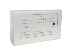
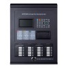
The fire alarm repeater panel works with conventional fire alarm control panel via RS485 communication.
It has 16 zones alarm and fault indication.
It works by 24V power supply and with test button, reset button and mute button
1. Repeater Status Indication and button operation
FIRE ALARM Status: When a fire alarm occurs, the corresponding zone red LED flashing and the internal buzzer sounds. When “MUTE/TEST” button pushed, the alarm zone LED lights steady and the buzzer silenced. When another new fire alarm occurs, the new zone red LED flash and the buzzer sound again. In the fire alarm status, the fire alarm “FIRE OUT” relay active and output “NO, NC, C” relay contacts.
FAULT Status:When a fault event occurs, the corresponding zone’s yellow LED flashing and the internal buzzer sounds. When “MUTE/TEST” button pushed, the fault zone LED lights steady and the buzzer silenced. When another new fault event occurs, the new zone yellow LED flash and the buzzer sound again. In the fault alarm status, the fault alarm “FAULT OUT” relay active and output “NO, NC, C” relay contacts.
Normal Status:When fire alarm panel’s fire or fault event restored, the fire alarm panel would send commands to let the repeater to the Normal Status.
POWER LED: The “POWER” LED would keep light steady when the power supply in normal status.
COMM LED: The “COMM” LED would flash once
TEST LAMP: In normal status, press “MUTE/TEST” button would have a lamp test.
http://www.vedardalarm.com/fire-floor-displayer-conventional-fire-alarm-repeater-16-zones-p-193
l MUTE SOUND: In fire or fault status, press “MUTE/TEST” button would silence the alarm sound
2. Repeater Installation
2.1 Terminal diagram:
l RS485 Communication Wire: The twisted shield wire (RVSP type) should be used as RS485 communication wire.
l EOF 120 ohm resistor: The last one repeater in the communication RS485 wire should set the JUMP
upc code: 782123753727
ean code: 0782123753727


